

In the 555 astable mode, the IC puts out a continuous stream of rectangular pulses having a specified frequency.
555 Astable Mode
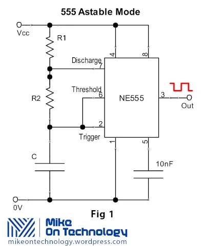 Resistor R1 is connected between Vcc and the discharge pin (pin 7) and another resistor (R2) is connected between the discharge pin (pin 7), and the trigger (pin 2) and threshold (pin 6) pins that share a common node.
Hence the capacitor is charged through R1 and R2, and discharged only through R2. Pin 7 has a low impedance to ground during the output low intervals of the cycle, therefore capacitor C is discharged.
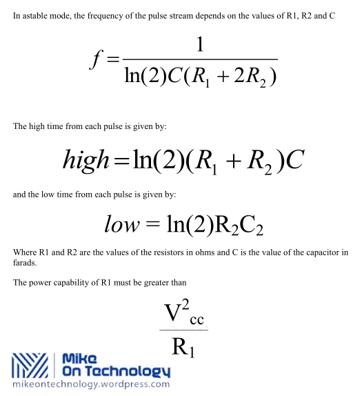
In astable mode the frequency of the pulse stream depends on the values of R1, R2 and C:
Particularly with bipolar 555s low values of R 1 must be avoided so that the output stays saturated near zero volts during discharge, as assumed by the above equation. Otherwise the output low time will be greater than calculated above.
How the Astable Works
The first cycle will take appreciably longer than the calculated time. This is because the capacitor must charge from 0V to 2/3 of Vcc from power-up on the first cycle. However it only needs to charge from 1/3 of Vcc to 2/3 of Vcc on subsequent cycles.
Less than 50% duty cycle
To achieve a duty cycle of less than 50% a small diode (that is fast enough for the application) can be placed in parallel with R2. The cathode side then goes to the capacitor. This bypasses R2 during the high part of the cycle so that the high interval depends approximately only on R1 and C.
The presence of the diode causes a voltage drop that slows charging on the capacitor. The result is that the high time is longer than that expected and that often-cited.
ln(2)*R1C = 0.693 R1C. The low time will be the same as without the diode as shown above. With a diode, the high time is:
Where Vdiode is when the diode has a current of 1/2 of Vcc/R1. This can be determined from its datasheet or by testing. As an extreme example, when Vcc= 5 and Vdiode= 0.7, high time = 1.00 R1C which is 45% longer than the “expected” 0.693 R1C.
At the other extreme when Vcc= 15 and Vdiode= 0.3, the high time = 0.725 R1C. This is closer to the expected 0.693 R1C. The equation reduces to the expected 0.693 R1C if Vdiode= 0.
Reset mode operation varies between manufacturers
The operation of RESET in this mode is not well defined. Some manufacturers’ parts will hold the output state to what it was when RESET is taken low. Others will send the output either high or low.
