
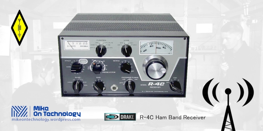
The Drake R-4C receiver is a 1970’s triple conversion superheterodyne receiver for the amateur bands 80 through 10 meters. Additional (optional) coverage of the general shortwave bands is possible by adding up to 15 crystals.
This article takes a look at this Drake receiver from the years when thermionic valves were still the norm. First there’s a general description followed by a more technical discussion. You will also find block and circuit diagrams, and specifications. As well, there is a link to download a PDF version of the original instruction manual.
Finally you can watch and listen to a Drake R-4C receiver in operation.
Drake R-4C Receiver in Detail
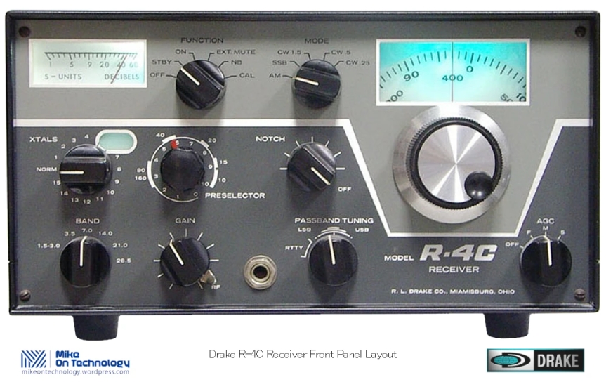
Starting with the front panel of the Drake R-4C receiver you’ll notice immediately the distinctive Drake dark grey, light grey and white colour scheme. It’s a smart of piece of kit, however by the early 1970’s it is already starting to look like a previous generation radio. It wasn’t much longer before the heavy sharp rectangular shapes and screws in the front panel gave way to more modern and more compact looking equipment.
The large main tuning dial is position to the right with the dial, which when illuminated has a blue tinge, immediately above it. An s-meter is place in the upper left corner, with the function and mode switches between the meter and the dial.
The next row down from the left; First the switch for the VFO or 15 optional crystals, then the RF preselector. The last control in this row is the notch filter knob.
Down to the bottom row; From the left side we have the band switch, gain control followed by a phono jack followed by the pass band tuning control. Finally, the last control on the right side is the AGC control.
Circuit Description
The description of the circuit operation included here is basically a summary of the information contained in the Drake R-4C receiver instruction manual.
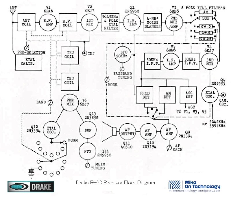
Refer to the Drake R-4C receiver block diagram above and the schematic circuit diagram below (Note: click the image to open a larger diagram for clarity).
RF Amplifier
Signal from the antenna passes through an RF tuning circuit before being fed to V1, a 6BA6 vacuum tube. Signal then goes to another tuned circuit before going to the 1st mixer V2 6EJ7) where it is mixed with the filtered output from the VFO. The VFO is tuning range is from 4955 kHz to 5455 kHz. Output from the VFO is applied to the cathode of V6.
Premixer
Output from crystal controlled oscillator Q12 is applied to the grid of V6. Crystal selection to control oscillator Q12 is determined by the settings of the crystals and band switches. The frequency of the crystal oscillator is always such that the difference frequency obtained by heterodyning the output of the VFO with the output of Q12 will always be 5645 kHz higher in frequency than the desired signal frequency.
First Mixer Stage
Output from premixer V6 is coupled to the 1st mixer V2 through the permeability tuned premixer output coils. RF coils T1 and T2 as well as the premixer output coils &3, T4 are gang tuned. Gang tuning maintains a fixed frequency relationship among these variable circuits.
V2 output is applied to the input of the 4 pole crystal lattice filter. The bandwidth of this filter is ±8 kHz.
Drake R-4C Receiver First IF System
Signal from the crystal filter at 5645 kHz is applied to the gate of FET Q1. This stage amplifies the 5645 kHz signal then feeds it first through the noise blanker (if used), then to grid 1 of the 2nd IF mixer tube V3. The IF signal is mixed with the beat frequency oscillator (BFO).
In SSB and CW modes the output from V3 is the sum of the IF signal and the BFO. This is approximately 5695 kHz depending on the setting of the Pass-band Tuning control. In AM mode the BFO is off and V3 functions as a buffer amplifier with its output at 5645 kHz.
Output from V3 feeds through the Mode selector switch to the appropriate 8 pole crystal filter for SSB and CW modes. AM is either fed directly to the V4 stage or if the AM filter is installed, then the signal goes to this filter first.
Output from the crystal filter then goes to the grid of V4 via the mode switch. In V4 the 5695 kHz signal is mixed with the 5645 kHz oscillator for SSB and CW modes. In AM mode the the 5645 kHz signal is mixed with a 5595 kHz oscillator signal. Output from V4 is tuned to the difference frequency of 59 kHz by IF transformer T7C. T7C Q factor is changed by the position of the mode switch. In CW 0.5 or 0.25 the high Q tap is connected to provide additional selectivity.
2nd IF System and Detectors
The 59 kHz signal from T7C is coupled to the grid of V5 through T-notch filter T8 and associated circuitry. V5 further amplifies the IF signal before it goes to the detectors. From there the signal path is set by the mode switch.
- In AM the BFO is off. Detection is then done by diode CR4 and the resulting audio gets amplified by Q6.
- In SSB and CW modes the BFO is on and BFO and IF both feed the product detector diodes CR2 and CR3.
The mode switch also selects the audio from either Q6 for AM or the product detector to send to the audio amp.
AGC Circuit
Output from the 50 kHz IF amplifier V5 is also applied to the AGC detector transistor Q7. Q7 is biased past cutoff under no signal conditions. As the amplitude of the signal from V5 increases a point is reached where where Q7 begins to conduct during a portion of the cycle. This results in a negative voltage developing across resistor R50.
Depending on the AGC switch selection a combination of capacitors C73, C74, and C76 are charged by this DC voltage. As the release time of the AGC is determined by this capacitor combination as well as R50. This negative going voltage is applied to filtering and delay networks before going to the grids of V1, V3 and V5.
Counterclockwise rotation of the RF Gain control increase negative bias on the AGC controlled stages thereby limiting the gain. Isolating the mute line from ground lets the AGC line voltage swing to -40 V which cuts off the receiver stages thereby muting the receiver.
The S Meter
The S meter is across a bridge circuit that uses the plate of V5 as one arm of the bridge and the plates of V2 and V4 as the other arm. Increasing signal strength causes AGC voltage to be applied to the grid of V5 causing plate current to decrease. This unbalances the bridge thereby causing the S meter to deflect up scale.
The 2 potentiometers R32 and R33 set the bridge balance point thereby determining the zero setting of the circuit. Sensitivity of the S meter is set by series potentiometer R36.
Audio Amp Stage
The AF amp is a direct coupled class A transformer output amplifier which consists of Q9, Q10, Q11 and Q13 and associated components. Transformer T13 has 2 windings. One of these matches a speaker or headphone output while the other is a high impedance winding for antivox voltage.
Gain is controlled by the AF Gain control R72 at the input of Q9. Negative feedback reduces distortion and improves amplifier stability.
Power Supply
Transformer T14 supplies 150 VDC from a full wave rectifier as well 12 VDC from another full wave rectifier circuit. Q2, C166 and R226 creates a filter to reduce ripple on the 12 V supply.
Crystal Calibrator
Q14 is a crystal oscillator running at 100 kHz. Q15 shapes the waveform to trigger the first J-K flip-flop in U1. The 100 kHz signal is applied to the IC clock input which causes the flip-flop to change state once every cycle, thus dividing by 2.
Output from the 1st flip-flop is applied to the input of the 2nd flip-flop which again divides by 2. The output of this flip-flop is a 25 kHz square wave that is applied to the receiver antenna via a coupling network
Circuit Schematic Diagram
Unfortunately the quality of the circuit diagram was too poor for me to clean up more than I did, but hopefully it at least gives you a place to start.

