
My Kenwood TR-7625 transceiver review includes a general description, circuit operation, documentation downloads and specifications.
Kenwood TR-7625 2m Mobile FM Transceiver Review
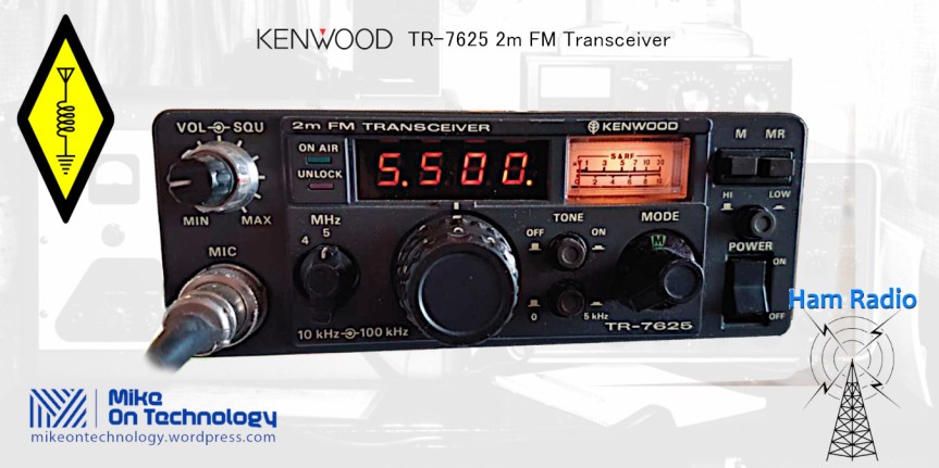
The Kenwood TR-7625 is a digitally synthesized FM mode transceiver for the 2 metre amateur radio band. The TR-7625 transmitter puts out a selectable 5W or 25W RF power to the antenna. Its less powerful brother radio, the TR-7200 only 1W or 10W output maximum output, but otherwise is identical to the TR-7625
Frequency range is 144 – 146 Mhz for the South African and EU markets but covers 144 – 147.995 MHz for the USA market.
The package comes complete with a strong vehicle mounting bracket which featured 2 lockable clips. It takes only seconds to remove the transceiver from the vehicle to take into the shack.
Front Panel Controls

A four digit LED frequency display is centrally placed on the upper front panel. Tuning steps are every 5 kHz across the band. Directly beneath the frequency display are the frequency selection controls. To the left a rotary switch selects the first 3 MHz values, for example; 144 MHz, 145 MHz (and 146 / 147 MHZ USA only). to the right of this switch a large control knob sets the 100 kHz steps while a push button switch is used for the 0.5 kHz step.
Rear Panel and Inside the Transceiver
The back panel of the Kenwood TR-7624 features a large prominent heatsink, the standard SO-239 UHF type antenna connector, a connector socket for the RM-76 remote control unit,2.5mm external speaker jack, a connection point for a tone pad along with the DC power supply socket.


Inside the TR-7625 you’ll find a rightly packed circuit board. The appearance of the insides of the Kenwood TR-7625 transceiver looks really well made creating an impression of good quality.
 A built in loudspeaker is mounted on the top panel which is great in the shack providing clear, low distortion audio.
However this top position doesn’t work out great when the transceiver is installed under a vehicle’s dashboard. However, a good speaker made for mobile radio communication improves matters a great deal.
As an aside, I had a neat external Bosch round commercial radio speaker mounted in my vehicle which directed the sound straight at me. This arrangement made a world of difference to mobile operating with the Kenwood TR-7625.
Kenwood TR-7625 Circuit Operation
The Kenwood TR-7625 is a 25W multi channel (400 channels between 144 and 146 Mhz for SA and Europe, 800 channels 144 to 148 Mhz in the USA) transceiver. The transceiver features a built in repeater shift circuit along with a memory circuit along with provision to connect a remote control unit.
Frequency control employs a PLL circuit using a SM5111A IC for the programmable counter, reference oscillator, frequency divider and phase detector. This item is probably no longer available from manufacturers stocks.
Block Diagram

Phased Locked Loop (PLL) Circuit
The 130 Mhz signal from the VCO Q27 passes through a buffer Q28 and is then divided into synthesizer output by Q11 and a loop output at Q12. Q12 output is mixed with the local oscillator output. This is then tripled by Q6, D21 and Q20 to achieve IF frequency.
IF frequency is amplified by Q19 then goes to Q15 where the output is frequency divided as set by the BCD code, and compared with the 10 kHz reference frequency (which is 1/1024 of 10.240 MHz).
The frequency division ratio, memory and remote indication functions are controlled by BCD codes.
+5 kHz Circuit
Reference frequency in the PLL is controlled in 10 kHz steps. The +5 kHz step is controlled by varying the frequency of the local xtal oscillator by varicap diode. Therefore the frequency division ratio remains unchanged when the +5 kHz frequency step is activated.
The memory circuit also included the same bit so it functions even when the +5 k#hz circuit is active.
Repeater Shift Circuit
Transmit frequencies are shifted for repeater use by changing the local oscillator xtal frequency as shown below
My Kenwood TR-7625 transceiver review includes a general description, circuit operation, documentation downloads and specifications.
Kenwood TR-7625 2m Mobile FM Transceiver Review
The Kenwood TR-7625 is a digitally synthesized FM mode transceiver for the 2 metre amateur radio band. The TR-7625 transmitter puts out a selectable 5W or 25W RF power to the antenna. Its less powerful brother radio, the TR-7200 only 1W or 10W output maximum output, but otherwise is identical to the TR-7625
Frequency range is 144 – 146 Mhz for the South African and EU markets but covers 144 – 147.995 MHz for the USA market.
The package comes complete with a strong vehicle mounting bracket which featured 2 lockable clips. It takes only seconds to remove the transceiver from the vehicle to take into the shack.
Front Panel Controls
A four digit LED frequency display is centrally placed on the upper front panel. Tuning steps are every 5 kHz across the band. Directly beneath the frequency display are the frequency selection controls. To the left a rotary switch selects the first 3 MHz values, for example; 144 MHz, 145 MHz (and 146 / 147 MHZ USA only). to the right of this switch a large control knob sets the 100 kHz steps while a push button switch is used for the 0.5 kHz step.
Rear Panel and Inside the Transceiver
The back panel of the Kenwood TR-7624 features a large prominent heatsink, the standard SO-239 UHF type antenna connector, a connector socket for the RM-76 remote control unit,2.5mm external speaker jack, a connection point for a tone pad along with the DC power supply socket.
Inside the TR-7625 you’ll find a rightly packed circuit board. The appearance of the insides of the Kenwood TR-7625 transceiver looks really well made creating an impression of good quality.
A built in loudspeaker is mounted on the top panel which is great in the shack providing clear, low distortion audio.
However this top position doesn’t work out great when the transceiver is installed under a vehicle’s dashboard. However, a good speaker made for mobile radio communication improves matters a great deal.
As an aside, I had a neat external Bosch round commercial radio speaker mounted in my vehicle which directed the sound straight at me. This arrangement made a world of difference to mobile operating with the Kenwood TR-7625.
Kenwood TR-7625 Circuit Operation
The Kenwood TR-7625 is a 25W multi channel (400 channels between 144 and 146 Mhz for SA and Europe, 800 channels 144 to 148 Mhz in the USA) transceiver. The transceiver features a built in repeater shift circuit along with a memory circuit along with provision to connect a remote control unit.
Frequency control employs a PLL circuit using a SM5111A IC for the programmable counter, reference oscillator, frequency divider and phase detector. This item is probably no longer available from manufacturers stocks.
Block Diagram
Phased Locked Loop (PLL) Circuit
The 130 Mhz signal from the VCO Q27 passes through a buffer Q28 and is then divided into synthesizer output by Q11 and a loop output at Q12. Q12 output is mixed with the local oscillator output. This is then tripled by Q6, D21 and Q20 to achieve IF frequency.
IF frequency is amplified by Q19 then goes to Q15 where the output is frequency divided as set by the BCD code, and compared with the 10 kHz reference frequency (which is 1/1024 of 10.240 MHz).
The frequency division ratio, memory and remote indication functions are controlled by BCD codes.
+5 kHz Circuit
Reference frequency in the PLL is controlled in 10 kHz steps. The +5 kHz step is controlled by varying the frequency of the local xtal oscillator by varicap diode. Therefore the frequency division ratio remains unchanged when the +5 kHz frequency step is activated.
The memory circuit also included the same bit so it functions even when the +5 k#hz circuit is active.
Repeater Shift Circuit
Transmit frequencies are shifted for repeater use by changing the local oscillator xtal frequency as shown below
| 144 and 145 MHz Bands | |
| [ – ] Shift | 43.5667 MHz |
| [ S ] | 43.7667 MHz |
| [ + ] Shift | Not available for these bands |
| 144 and 145 MHz Bands | |
| [ – ] Shift | 44.2333 MHz |
| [ + ] Shift | 44.6333 MHz |
| [ S ] | 44.4333 MHz |
Memory Shift
Memory shift (M on shift selector) shifts the the transmitter frequency to the memory frequency.
Control Unit
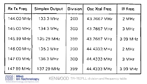
Frequency settings are made using the MHz, 100 kHz and 10 kHz rotary switches. The relationship between the frequency and frequency division is shown here.
| 144 and 145 MHz Bands | |
| 144.ooo MHz | 200 |
| 145.ooo MHz | 300 |
| 145.99o MHz | 399 |
| 146.ooo MHz | 200 |
| 147.ooo MHz | 300 |
| 147.99o MHz | 399 |
Audio from the microphone passes through a limiter amplifier and then FM modulates the 10.700 MHz oscillator. The resulting modulated signal is then mixed with the local oscillator signal to obtain the 144 – 146 MHz signal.
A variable band pass filter (B.P.F) provides power and good spurious characteristics by the use of VCO voltage. The RF Power stage uses an M57712H VHF power module from Mitsubishi to provide high reliability.

Kenwood TR-7625 Receiver Circuit
The received signal from the antenna passes through the diode Tx/Rx antenna switch then goes to the 2 stage antenna tuning unit (A.T.U.), a 3 stage helical tuned circuit with MOSFET RF preamplifier. From here the signal goes to the MOSFET mixer where it gets converted to 10.7 MHz I.F. frequency.

This converted signal then passes through a 2 stage filter 10.7Mhz I.F. before being fed to mixer 2 where it is converted to the second I.F. stages 455 kHz signal. This is then passed through a 455 kHz ceramic filter then converted to A.F. by the ceramic discriminator.
After this the A.F. signal is amplified by an audio power stage to drive a speaker.
Receiver Squelch
The receiver uses a noise amplification type of squelch circuit. Noise component in the squelch signal from the discriminator is picked up by the circuit which amplifies and rectifies this signal to control the first A.F. amplifier stage.
Full Circuit Diagram
The full size version of this diagram may be downloaded from the link here below.

Kenwood TR-7625 Specifications
| Type: | Amateur VHF transceiver | ||
| Frequency range: | 144-146 MHz (Europe) 144-148 MHz (USA) |
||
| Tuning steps: | 5 / 10 / 100 KHz | ||
| Mode: | FM | ||
| Channels/memory management: | 1 regular RAM (external backup power needed) |
||
| Repeater shift/offset: | ±600 KHz | ||
| Power supply: | 11.5-16 VDC | ||
| Current drain/power consumption: | RX: Max 500 mA (no signal) TX: 3-6 A |
||
| Antenna impedance/connector: | 50 ohms / SO-239 | ||
| Dimensions (W*H*D): | 161*61*230 mm (6.34*2.4*9.05″) | ||
| Weight: | 1.75 Kg (3.85 lbs) | ||
| Other features: | CTCSS/PL option (USA) 1750 Hz tone burst (Europe) |
||
| RECEIVER SECTION | |||
| Receiver system: | Double conversion superheterodyne 1st IF: 10.7 MHz 2nd IF: 455 KHz |
||
| Sensitivity: | 0.4 uV (20 dB quieting) | ||
| Selectivity: | 12 KHz (-6 dB) | ||
| Image rejection: | 70 dB | ||
| AF output power/speaker: | 1.5 W at 10% distortion / 8 ohms | ||
| External speaker connector: | 3.5 mm, 8 ohms | ||
| TRANSMITTER SECTION | |||
| RF output power: | Hi: 25 W Lo: 5 W |
||
| Modulation system: | Variable reactance direct shift | ||
| Max FM deviation: | ±5 KHz | ||
| Spurious emissions: | Less than -60 dB | ||
| Microphone impedance/connector: | 500 ohms / 4-pin | ||
| MISCELLANEOUS | |||
| Manufactured: | Japan, 19xx-19xx (Discontinued) | ||
| Additional info: | |||
| Related documents: | User manual (3.8 MB) | ||
| Modifications: | |||
| Options/Accessories: |
|
Weak Point
There was a common weakness with this product, the microphone. The microphone I got delivered with my Kenwood TR-7625 was a fairly small unit which lacked a feel of quality out of line with the rest of the package. Later releases had a different, more normal sized mic.
I didn’t have it too long when it started crackling. As it turned one of the soldered cable connections to the microphone had a dry joint, so it was definitely a factory defect. As the transceiver was still under guarantee I took it in to the agent I bought it from in Johannesburg, Julius Liebermann.
Umm, not too helpful I’m afraid. They weren’t interested in doing anything about it. Anyway, arguing was fruitless, but they did let me use a soldering iron to fix the thing myself. That was the last thing I ever purchased from that store. Some years later when I was selling Kenwood commercial radios I dealt with the SA agent in Pretoria directly which upset the JL crowd as they thought they were the sole Jhb area dealership for these products too.
Anyway, looking at user experiences posted online the bug with the microphones remained the most common cause for complaint. Several articles mentioned the PTT microswitch failing, which was not available as a spare? And then the high price to replace the entire microphone with an original part.
Current Availability and Prices
I found a couple of these transceivers on ebay.com. Prices ranged from R2700.00 for a clean radio in what looked like excellent condition down to R 900.00 for another which had seen good use, was complete with fittings but did not include the microphone. Estimated delivery charges were in the region of R 965.00 from the USA to South Africa.
These prices are based on todays forex exchange rate (22 March 2022).
Then you’ll still have to pay the 14& VAT to SARS bringing the total purchase cost to between R 2890.00 and R 4690.00
A good price for a used Kenwood TR-7625 sold in South Africa could be anything less than these prices. In my opinion fair price for these transceivers would be in the region of R2500.00 in good working condition. That’s how much I would be prepared to pay if I was in the market for one of these old radios.
